
Onhlp.com


Disassembly
- Before the following disassembly, power switch is set to off and disconnected the power cord.
Mechanical parts
1. Front grille
1. Open the inlet grille upward or downward.
2. Remove the screw which fastens the front grille.
3. Pull the front grille from the right side.
4. Remove the front grille.
5. Re-install the component by referring to the removal procedure.
NOTICE Mark Δ of inlet grille means opening direction.

2. Cabinet
1. After disassembling the front grille, remove the screws which fasten the cabinet at both sides. Keep these for later use.
2. Remove the two screws which fasten the cabinet at back.
3. Pull the base pan forward.
3. Control box
1. Remove the front grille.
2. Pull the base pan forward so that you can remove the 2 screws which fasten the cover control at the right side.
3. Remove the 3 screws which fasten the controlbox.
4. Discharge the capacitor by placing a 20,000 ohm resistor across the capacitor terminals.
5. Disconnect two wire housings in the control box.
6. Pull the control box forward completely.
7. Re-install the components by referring to the removal procedure.
(Refer to the wiring diagram found on page 29~30 in this manual and on the control box.)
Air handling parts
4. Cover (at the top)
1. Remove the front grille. (Refer to section 1)
2. Remove the cabinet. (Refer to section 2)
3. Remove 11 screws which fasten the brace and covers.
4. Remove the covers and the brace.
5. Re-install the components by referring to the removal procedure, above.
5. Blower
1. Remove the cover. (Refer to section 4)
2. Remove the 3 screws which fasten the evaporator at the left side and the top side.
3. Move the evaporator sideward carefully.
4. Remove the 2 terminals carefully.
5. Remove the 3 screws which fasten the Heater Cover.
6. Remove the Heater Cover.
7. Remove the orifice from the air guide carefully.
8. Remove the clamp which secures the blower with plier.
9. Remove the blower with plier or your hand without touching blades.
10. Re-install the components by referring to the removal procedure, above.
6. Fan
1. Remove the cabinet. (Refer to section 2)
2. Remove the brace and shroud cover. (Refer to section 4)
3. Remove the side cover with 2 screws.
4. Remove the 5 or 6 screws which fasten the condenser.
5. Move the condenser sideways carefully.
6. Remove the clamp which secures the fan.
7. Remove the fan.
8. Re-install the components by referring to the removal procedure, above.
7. Shroud
1. Remove the fan. (Refer to section 6)
2. Remove the 2 screws which fasten the shroud.
3. Remove the shroud.
4. Re-install the component by referring to the removal procedure, above.
Electrical parts
8. Motor
1. Remove the cabinet. (Refer to section 2)
2. Remove the cover control and disconnect a wire housing in control box. (Refer to section 3)
3. Remove the blower. (Refer to section 5)
4. Remove the fan. (Refer to section 6)
5. Remove the 4 screws which fasten the motor.
6. Remove the motor.
7. Re-install the components by referring to the removal procedure, above.
9. Compressor
1. Remove the cabinet. (Refer to section 2)
2. Discharge the refrigerant system using FreonTM Recovery System. If there is no valve to attach the recovery system, install one (such as a watco a-1) before venting the FreonTM . Leave the valve in place after servicing the system.
3. Disconnect the 3 leads from the compressor.
4. After purging the unit completely, unbraze the suction and discharge tubes at the compressor connections.
5. Remove the 3 nuts and the 3 washers which fasten the compressor.
6. Remove the compressor.
7. Re-instill the components by referring to the removal procedure, above.
10. CAPACITOR
1. Remove the control box. (Refer to section 3)
2. Remove the screw and knobs which fasten the display panel.
3. Disconnect the 2 leads from the rocker switch and remove the panel.
4. Remove a screw and unfold the control box.
5. Remove the screw and the clamp which fastens the capacitor. (See Fig. 27)
6. Disconnect all the leads of capacitor terminals.
7. Re-install the components by referring to the removal procedure, above.
11. POWER CORD
1. Remove the control box. (Refer to section 3)
2. Unfold the control box. (Refer to section 10)
3. Disconnect the grounding screw from the control box.
4. Disconnect 2 receptacles.
5. Remove a screw which fastens the clip cord.
6. Pull the power cord.
7. Re-install the component by referring to the removal procedure, above. (Use only one ground-marked hole for ground connection.)
8. If the supply cord of this appliance is damaged, it must be replaced by the special cord. (The special cord means the cord which has the same specification marked on the supply cord fitted to the unit.)
12. THERMISTOR
1. Remove the control box. (Refer to section 3)
2. Unfold the control box. (Refer to section 10)
3. Disconnect the thermistor terminals from main P.W.B assembly.
4. Remove the thermistor.
5. Re-install the components by referring to the removal procedure above.
13. SYNCHRONOUS MOTOR
1. Remove the control box. (Refer to section 3)
2. Unfold the control box. (Refer to section 10)
3. Remove the crankshaft.
4. Disconnect all the leads of the synchronous motor.
5. Remove the 2 screws which fasten the synchronous motor.
6. Re-install the components by referring to the removal procedure, above.
Refrigeration cycle
CAUTION: Discharge the refrigerant system using FreonTM Recovery System.If there is no valve to attach the recovery system, install one (such as a WATCO A-1) before venting the FreonTM. Leave the valve in place after servicing the system.
16. CONDENSER
1. Remove the cabinet. (Refer to section 2)
2. Remove the brace and the shroud cover. (Refer to section 4)
3. Remove 2 screws which fasten the side cover.
4. Remove the 5 or 6 screws which fasten the condenser.
5. After discharging the refrigerant completely, unbraze the interconnecting tube at the condenser connections.
6. Remove the condenser.
7. Re-install the components by referring to notes.
EVAPORATOR
1. Remove the cabinet. (Refer to section 2)
2. Remove the top cover and the brace. (Refer to section 4)
3. Discharge the refrigerant completely.
4. Remove the 3 screws which fasten the evaporator at the left side and the top side.
5. Move the evaporator sideward carefully and then unbraze the interconnecting tube at the evaporator connectors.
6. Remove the evaporator.
7. Re-install the components by referring to notes.
18. CAPILLARY TUBE
1. Remove the cabinet. (Refer to section 2)
2. Remove the brace. (Refer to section 4)
3. After discharging the refrigerant completely, unbraze the interconnecting tube at the capillary tube.
4. Remove the capillary tube.
5. Re-install the components by referring to notes.
You can reach detailed information about air conditioner installation at this address.
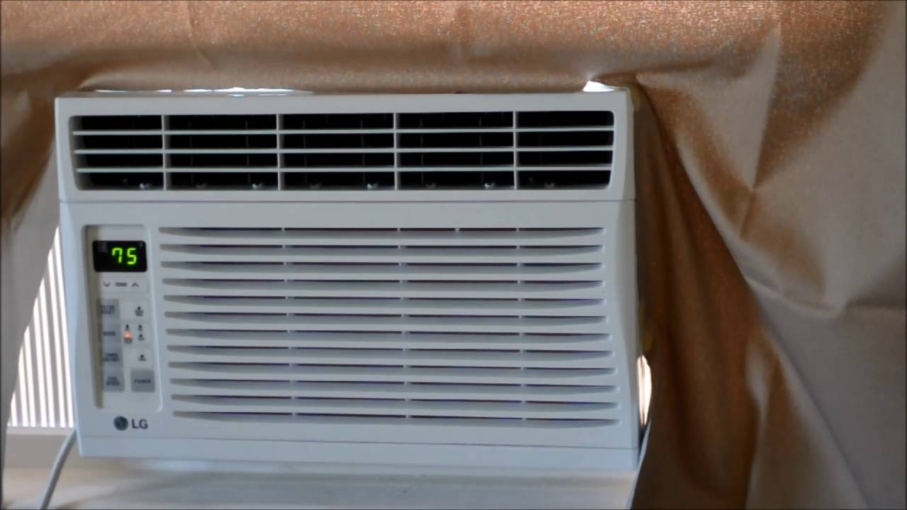
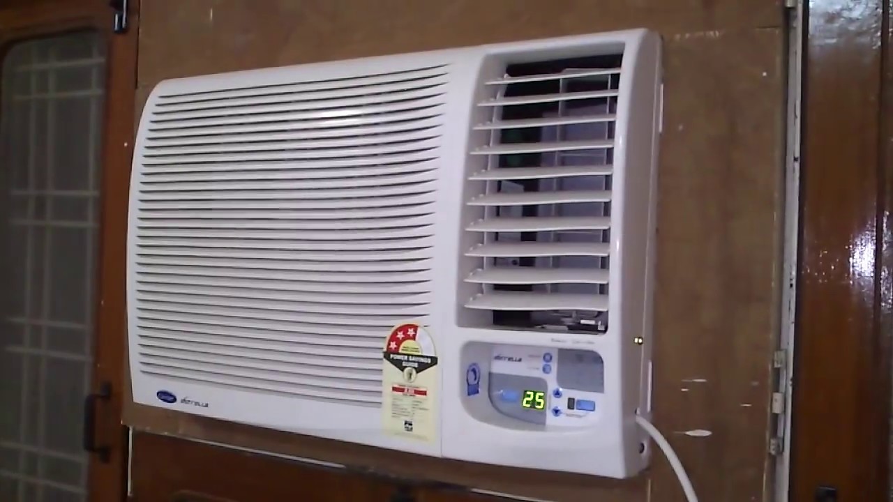
LG Room Air Conditioner Installation Operations
Published: Friday, July 12, 2019 Viewed 110 times.
Ask me about:
A good air conditioner can help make those hot summers much more bearable. The LG LW8016ER Air Conditioner is the best window AC you can buy, with its three cooling speeds and built-in dehumidifier.
If the unit displays the error code E5, the water reservoir is full inside the unit, indicating a need to drain the water. Please see “Draining the air conditioner” in the User Guide.
LG Split System Air Conditioner Error code = 05
LG AC Fault Definition = Communication(Indoor Outdoor) – Communication Issue. Indoor Status = Off.
If your thermostat is near the air vents, it can think your surroundings are cool and shut down the AC. The air filter might have gone dirty. In fact, a dirty filter is one of the most common causes in regular AC problems. A dirty filter blocks the air flow and can make your AC turn off.
LG AC CH34 Error Code = ABNORMAL PRESSURE/OVERHEATING. This error displays if the SAFETY RELAY powers the unit down due to ABNORMAL PRESSUREbuilding within the sealed system. This feature is built into the unit to combat overheating issues.

Askme / 7/12/2019 8:31:26 AM (Original: 1280X720 px)

Askme / 7/12/2019 8:31:48 AM (Original: 1280X720 px)

Askme / 7/12/2019 8:32:17 AM (Original: 1280X720 px)
Learn how the diagnostic LEDs on the GA-990FX-Gaming motherboard can help troubleshoot hardware issues by indicating specific problem areas for effective troubleshooting.
/ GA-990FX-Gaming motherboard diagnostic LEDs Answers: 1 118
Learn how the diagnostic LEDs on the GA-990FX-Gaming motherboard can help troubleshoot hardware issues by indicating specific problem areas for effective troubleshooting.
/ GA-990FX-Gaming motherboard diagnostic LEDs Answers: 1 185
Learn how to find the Comcast wireless network key easily and connect your device to the internet for seamless browsing and streaming.
/ Comcast wireless network key Answers: 1 54
If you have forgotten your Comcast router login information, you can easily retrieve it by following a few simple steps. Learn more here.
/ Comcast router login information Answers: 1 48
Learn why your Xiaomi phone is not detecting your SIM card and how to troubleshoot this problem like a pro. Follow these tips to fix the issue quickly.
/ Xiaomi SIM card not working Answers: 1 36
Learn how to reset your Google account on an LG Stylo without losing any data or settings. Follow simple steps to maintain your information intact.
/ LG Stylo Google account reset Answers: 1 39
Learn how to safely remove your Google account from your LG Stylo device without losing any data or resorting to a factory reset.
/ LG Stylo Google account removal Answers: 1 57
Learn how to troubleshoot error codes on the GA-990FX-Gaming motherboard with these common steps. Ensure a smooth troubleshooting process for your system.
/ GA-990FX-Gaming motherboard error code chart Answers: 1 48
Recover your forgotten Comcast broadband password to easily regain access to your internet connection. Follow the steps provided to reset your password.
/ Comcast broadband password recovery Answers: 1 59
Learn how to activate a SIM card on your Xiaomi device easily with these tips. Ensure smooth functionality and stay connected hassle-free!
/ Xiaomi SIM card activation tips Answers: 2 45
Discover common troubleshooting steps for issues with the Gigabyte GA-990FX-Gaming motherboard and learn how to resolve them effectively.
/ Gigabyte GA-990FX-Gaming motherboard troubleshooti Answers: 1 26
Forgot your Comcast Wi-Fi passphrase? Learn how to retrieve it effortlessly with our step-by-step guide. Say goodbye to connectivity issues!
/ Comcast Wi-Fi passphrase retrieval Answers: 1 28
Learn how to connect your Stylo 4 to your TV without using internet with simple methods like using an HDMI cable or a wireless display adapter.
/ Stylo 4 to TV without internet Answers: 1 26
Having trouble activating your SIM card on your Xiaomi device? Follow these steps to troubleshoot and get your device up and running in no time.
/ Xiaomi SIM card activation troubleshooting Answers: 1 28
Secure your Comcast modem by changing the default access code for better security. Find out the default code and step-by-step instructions to change it here.
/ Comcast modem access code Answers: 1 31
onhlp.com: Your Questions and Answers Resource with a Wealth of General Knowledge
Are you seeking a one-stop destination for comprehensive knowledge and answers to your burning questions? Look no further than onhlp.com! Our platform is your go-to source for a wide range of information, all conveniently presented in an easily accessible question and answer format.
At onhlp.com, we pride ourselves on being your reliable knowledge hub. Whether you're curious about technology, science, history, or any other subject under the sun, our extensive General Knowledge (GK) knowledge base has you covered. We've made it our mission to provide you with in-depth insights and facts on an array of topics. Read more
