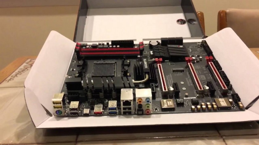
GIGABYTE GA-990FX-Gaming Motherboard Hardware Installation
The motherboard contains numerous delicate electronic circuits and components which can become damaged
as a result of electrostatic discharge (ESD). Prior to installation, carefully read the user's manual and follow these procedures:
- Prior to installation, make sure the chassis is suitable for the motherboard.
- Prior to installation, do not remove or break motherboard S/N (Serial Number) sticker or warranty sticker provided by your dealer. These stickers are required for warranty validation.
- Always remove the AC power by unplugging the power cord from the power outlet before installing or removing the motherboard or other hardware components.
- When connecting hardware components to the internal connectors on the motherboard, make sure they are connected tightly and securely.
- When handling the motherboard, avoid touching any metal leads or connectors.
- It is best to wear an electrostatic discharge (ESD) wrist strap when handling electronic components such as a motherboard, CPU or memory. If you do not have an ESD wrist strap, keep your hands dry and first touch a metal object to eliminate static electricity.
- Prior to installing the motherboard, please have it on top of an antistatic pad or within an electrostatic shielding container.
- Before connecting or unplugging the power supply cable from the motherboard, make sure the power supply has been turned off.
- Before turning on the power, make sure the power supply voltage has been set according to the local voltage standard.
- Before using the product, please verify that all cables and power connectors of your hardware components are connected.
- To prevent damage to the motherboard, do not allow screws to come in contact with the motherboard circuit or its components.
- Make sure there are no leftover screws or metal components placed on the motherboard or within the computer casing.
- Do not place the computer system on an uneven surface.
- Do not place the computer system in a high-temperature or wet environment.
- Turning on the computer power during the installation process can lead to damage to system components as well as physical harm to the user.
- If you are uncertain about any installation steps or have a problem related to the use of the product, please consult a certified computer technician.
- If you use an adapter, extension power cable, or power strip, ensure to consult with its installation and/or grounding instructions.
GA-990FX-Gaming Motherboard CPU
AM3+ Socket:
- AMD AM3+ FX processor
- AMD AM3 Phenom™ II processor/ AMD Athlon™ II processor
(Go to GIGABYTE's website for the latest CPU support list.)
Hyper Transport Bus: 5200 MT/s
GA-990FX-Gaming Motherboard Chipset
North Bridge: AMD 990FX
South Bridge: AMD SB950
GA-990FX-Gaming Motherboard Memory
- 4 x DDR3 DIMM sockets supporting up to 32 GB of system memory(DuetoaWindows 32-bit operating system limitation, when more than4GBofphysicalmemory is installed, the actual memory size displayed will be less than the size of the physical memory installed.)
- Dual channel memory architecture
- Support for DDR3 2000(O.C.)/1866/1600/1333/1066 MHz memory modules(Tosupport aDDR3 1866 MHz(andabove) memory, youmust install anAM3+ CPU first.)
- Support for Extreme Memory Profile (XMP) memory modules (Go to GIGABYTE's website for the latest supported memory speeds and memory modules.)
GA-990FX-Gaming Motherboard Audio
- Realtek® ALC1150 codec
- TI Burr Brown®OPA2134 operational amplifier
- High Definition Audio2/4/5.1/7.1-channel
- Support for S/PDIF Out
GA-990FX-Gaming Motherboard LAN
Rivet Networks Killer™ E2201 LAN chip (10/100/1000 Mbit)
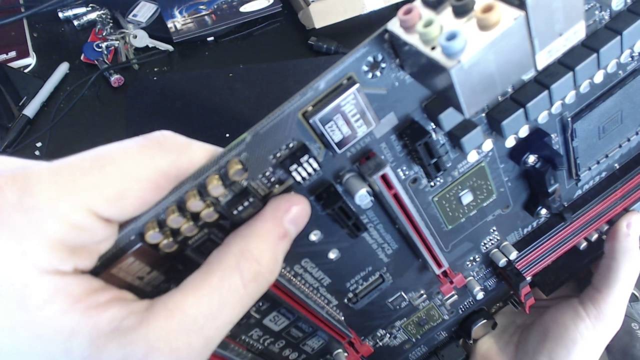
GA-990FX-Gaming Motherboard Expansion Slots
- 2 x PCI Express x16 slots, running at x16 (PCIEX16_1/PCIEX16_2) (For optimum performance, if only one PCI Express graphics card is to be installed, be sure to install it in the PCIEX16_1 slot; if you are installing two PCI Express graphics cards, it is recommended that you install them in the PCIEX16_1 and PCIEX16_2 slots.)
- 1 x PCI Express x16 slot, running at x4 (PCIEX4) (ThePCIEX4slotsharesbandwidth withthePCIEX1_3 slot. WhenPCIEX1_3ispopulated with aPCIExpressexpansioncard,thePCIEX4slotwilloperateatupto x2 mode.)
- 3 x PCI Express x1 slots (All of the PCI Express slots conform to PCI Express 2.0 standard.)
GA-990FX-Gaming Motherboard Multi-Graphics Technology
Support for 2-Way AMD CrossFire™ and 2-Way NVIDIA® SLI™ Technology
GA-990FX-Gaming Motherboard Storage Interface
South Bridge:
- 1 x M.2 connector (Socket 3, M key, type 2242/2260/2280 SATA and PCIe x4/x2/x1 SSD support)
- 6 x SATA 6Gb/s connectors
- Support for RAID 0, RAID 1, RAID 5, RAID 10, and JBOD (Refer to"1-9Internal Connectors," forthesupported configurations withtheM.2and SATA connectors.)
GIGABYTE GA-990FX-Gaming Motherboard USB
South Bridge: 12 x USB 2.0/1.1 ports (6 ports on the back panel, 6 ports available through the internal USB headers)
VIA® VL805 chip: 4 x USB 3.0/2.0 ports (2 ports on the back panel, 2 ports available through the internal USB header)
ASMedia® USB 3.1 Controller:
- 1 x USB Type-C™ port on the back panel, with USB 3.1 support
- 1 x USB 3.1 Type-A port (red) on the back panel
GIGABYTE GA-990FX-Gaming Motherboard Internal Connectors
- 1 x 24-pin ATX main power connector
- 1 x 8-pin ATX 12V power connector
- 1 x M.2 Socket 3 connector
- 6 x SATA 6Gb/s connectors
- 1 x CPU fan header
- 2 x system fan headers
- 1 x power fan header
- 1 x front panel header
- 1 x front panel audio header
- 1 x S/PDIF Out header
- 1 x USB 3.0/2.0 header
- 3 x USB 2.0/1.1 headers
- 1 x Trusted Platform Module (TPM) header
- 1 x serial port header
- 1 x Clear CMOS jumper
- 1 x audio gain control switch
- 1 x power button
- 1 x reset button
- 1 x Clear CMOS button
GIGABYTE GA-990FX-Gaming Motherboard Back Panel Connectors
- 1 x PS/2 keyboard/mouse port
- 1 x USB Type-C™ port, with USB 3.1 support
- 1 x USB 3.1 Type-A port (red)
- 2 x USB 3.0/2.0 ports
- 6 x USB 2.0/1.1 ports
- 1 x RJ-45 port
- 1 x optical S/PDIF Out connector
- 5xaudio jacks (Center/Subwoofer Speaker Out,Rear Speaker Out,LineIn, Line Out, Mic In)
GIGABYTE GA-990FX-Gaming Motherboard I/O Controller
iTE® I/O Controller Chip
GIGABYTE GA-990FX-Gaming Motherboard Hardware Monitor
- System voltage detection
- CPU/System temperature detection
- CPU/System/Power fan speed detection
- CPU overheating warning
- CPU/System/Power fan fail warning
- CPU/System fan speed control (Whether the fan speed control function is supported will depend on the cooler you install)
GIGABYTE GA-990FX-Gaming Motherboard BIOS
- 2 x 32 Mbit flash
- Use of licensed AMI UEFI BIOS
- Support for DualBIOS™
- PnP 1.0a, DMI 2.7, WfM 2.0, SM BIOS 2.7, ACPI 5.0

GIGABYTE GA-990FX-Gaming Motherboard Unique Features
Support for APP Center:
Available applications in APP Center may vary by motherboard model. Supported functions ofeach application mayalsovarydepending onmotherboard specifications.
- @BIOS
- Ambient LED
- Cloud Station
- EasyTune
- Game Controller
- Smart TimeLock
- Smart Recovery 2
- System Information Viewer
- USB Blocker
Support for Q-Flash
Support for ON/OFF Charge
Support for Smart Switch
Support for Xpress Install
GIGABYTE GA-990FX-Gaming Motherboard Bundled Software
Norton® Internet Security (OEM version)
GIGABYTE GA-990FX-Gaming Motherboard Operating System
Support for Windows 10/8.1/7
GIGABYTE GA-990FX-Gaming Motherboard BIOS SETUP
BIOS(BasicInputandOutputSystem)recordshardwareparametersofthesystemintheCMOSonthemotherboard.ItsmajorfunctionsincludeconductingthePower-OnSelf-Test(POST)duringsystemstartup,saving system parameters and loading operating system, etc. BIOS includes a BIOS Setup program that allows the user to modify basic system configuration settings or to activate certain system features.When the power is turned off, the battery on the motherboard supplies the necessary power to the CMOS to keep the configuration values in the CMOS.To access the BIOS Setup program, press the <Delete> key during the POST when the power is turned on.To upgrade the BIOS, use either the GIGABYTE Q-Flash or @BIOS utility.
- Q-Flash allows the user to quickly and easily upgrade or back up BIOS without entering the operating system.
- @BIOS is a Windows-based utility that searches and downloads the latest version of BIOS from the Internet and updates the BIOS.
Because BIOS flashing ispotentially risky, ifyoudonotencounter problems using thecurrent version ofBIOS, itisrecommended thatyounotflash theBIOS. Toflash theBIOS, doitwithcaution. Inadequate BIOS flashing may result in system malfunction. It is recommended that you not alter the default settings (unless you need to) to prevent system instability or other unexpected results. Inadequately altering the settings may result in system's failure to boot. If this occurs, try to clear theCMOS values andreset theboard todefault values. (Refer tothe"Load Optimized Defaults" section in this chapter or introductions of the battery/clear CMOS jumper in Chapter 1 for how to clear the CMOS values.)
GIGABYTE GA-990FX BIOS Startup Screen
The following startup Logo screen will appear when the computer boots.
Onthemain menu oftheBIOS Setup program, press arrow keystomove among theitems andpress <Enter> to accept or enter a sub-menu. Or you can use your mouse to select the item you want.
- When the system is not stable as usual, select the Load Optimized Defaults item to set your system to its defaults.
- The BIOS Setup menus described in this chapter are for reference only and may differ by BIOS version.
GIGABYTE GA-990FX BIOS M.I.T.
This section provides information on the BIOS version, CPU base clock, CPU frequency, memory frequency, total memory size, CPU temperature and CPU voltage, etc.
Whether the system will work stably with the overclock/overvoltage settings you made is dependent on your overall system configurations. Incorrectly doing overclock/overvoltage mayresult indamage toCPU, chipset, ormemory and reduce the useful life of these components. This page is for advanced users only and we recommend you not to alter the default settings to prevent system instability or other unexpected results. (Inadequately altering the settings may result in system's failure to boot. If this occurs, clear the CMOS values and reset the board to default values.)
M.I.T. Current Status: This screen provides information on CPU/memory frequencies/parameters.
Advanced Frequency Settings
- BCLK Clock Control:Allows you to manually set the CPU base clock in 1 MHz increments. (Default: Auto)Important:ItishighlyrecommendedthattheCPUfrequencybesetinaccordancewiththeCPUspecifications.
- CPU NorthBridge Frequency: Allows you to alter the North Bridge controller frequency for the installed CPU. The adjustable range is dependent on the CPU being installed.
- HT Link Frequency: Allows you to manually set the frequency for the HT Link between the CPU and chipset. The adjustable range is dependent on the CPU being installed. (Default: Auto)
- CPU Clock Ratio: Allows you to alter the clock ratio for the installed CPU. The adjustable range is dependent on the CPU being installed.
- CPU Frequency:Displays the current operating CPU frequency.
Advanced CPU Core Features
- CPU Clock Ratio, CPU Frequency: The settings above are synchronous to those under the same items on the Advanced Frequency Settingsmenu.
- Core Performance Boost: Allowsyoutodetermine whethertoenabletheCorePerformance Boost (CPB) technology, a CPUperformance-boost technology. (Default: Auto)
- CPB Ratio: AllowsyoualtertheratiofortheCPB. Theadjustablerangeisdependenton the CPU beinginstalled. (Default: Auto)
- CPU Unlock:Allows you to determine whether unlock hidden CPU cores. (Default: Disabled)
- Cool & Quiet: Enabled: LetstheAMD Cool'n'Quiet driver dynamically adjust theCPU clock and VID to reduce heat output from your computer and its power consumption. (Default). Disabled: Disables this function.
- C1E Support: Allows you to determine whether to let the CPU enter C1 mode in system halt state. When enabled, the CPU core frequency and voltage will be reduced during system halt state to decrease power consumption. (Default: Enabled)
- SVM: Virtualization enhanced by Virtualization Technology will allow a platform to run multiple operating systems and applications in independent partitions. With virtualization, one computer system can function as multiple virtual systems. (Default: Enabled)
- CPU core Control: Allows you to determine whether to manually enable/disable CPU cores. Automatic mode allows the BIOS toenable allCPU cores (number ofcores available depends ontheCPU being used). (Default: Automatic mode) Note: This item is present only when you install a CPU that supports this feature.
- Core C6 State: (This item is present only when you install a CPU that supports this feature.) Allows you to determine whether to let the CPU enter C6 mode in system halt state. When enabled, the CPU core frequency will be reduced during system halt state to decrease power consumption. The C6 state is a more enhanced power-saving state than C1. (Default: Enabled)
- HPC Mode: (This item is present only when you install a CPU that supports this feature.) Allows you to determine whether to enable High Performance Computing (HPC) mode for the CPU. Enabledprevents the CPU frequency from being lowered during system halt state. (Default: Disabled)
- APM (AMD Application Power Management): (This item is present only when you install a CPU that supports this feature.) Enabled: Dynamically monitors thepower consumption oftheCPU cores andautomaticallyoptimizes the CPU to its best performance level. (Default). Disabled: Disables this function.
- Extreme Memory Profile (X.M.P.): (This item is present only when you install a memory module that supports this feature)Allows theBIOS toreadtheSPDdataonXMP memory module(s) toenhance memory performance when enabled. Disabled: Disables this function. (Default) Profile1:Uses Profile 1 settings. Profile2: (This item is present only when you install a memory module that supports this feature)Uses Profile 2 settings.
- System Memory Multiplier: Allows you to set the system memory multiplier. Auto setsmemory multiplier according tomemory SPD data. (Default: Auto)
- Memory Frequency (MHz): This value is automatically adjusted according to the BCLK Clock Control and System Memory Multipliersettings.`Advanced Memory Settings
- Extreme Memory Profile (X.M.P.): (This item is present only when you install a memory module that supports this feature), System Memory Multiplier, Memory Frequency(MHz)The settings above are synchronous to those under the same items on the Advanced Frequency Settingsmenu.
- DRAM Timing Selectable: Quick and Expert allows thememory timing settings below tobeconfigurable. Options are:Auto(default), Quick, Expert.
- Profile DDR Voltage: When using a non-XMP memory module or Extreme Memory Profile (X.M.P.) is set to Disabled, the value isdisplayed according toyourmemory specification. When Extreme Memory Profile (X.M.P.) is set to Profile1 or Profile2, the value is displayed according to the SPD data on the XMP memory.
- Profile VTT Voltage: The value displayed here is dependent on the CPU being used.
- Channel Interleaving: Enables or disables memory channel interleaving. Enabled allows the system to simultaneously access different channels ofthememoryto increasememoryperformance andstability. AutoletstheBIOSautomatically configure this setting. (Default: Auto)
- Rank Interleaving: Enables or disables memory rank interleaving. Enabled allows the system to simultaneously access different ranks ofthememoryto increasememory performanceand stability. Auto lets the BIOSautomaticallyconfigure this setting. (Default: Auto)
- Channel A/B Timing Settings: Thissub-menuprovidesmemorytimingsettings foreach channelofmemory. Therespectivetimingsettingscreens areconfigurable onlywhen DRAM Timing Selectable is set to Quick or Expert. Note: Your system may become unstable or fail to boot after you make changes on the memory timings. If this occurs, please reset the board to default values by loading optimized defaults or clearing the CMOS values.
GIGABYTE GA-990FX BIOS BIOS Features
Boot Option Priorities: Specifies the overall boot order from the available devices. Removable storage devices that support GPT format will be prefixed with "UEFI:" string on the boot device list. To boot from an operating system that supports GPT partitioning, select the device prefixed with "UEFI:" string.Or if you want to install an operating system that supports GPT partitioning such as Windows 7 64-bit, select the optical drive that contains the Windows 7 64-bit installation disk and is prefixed with "UEFI:" string.
Hard Drive/CD/DVD ROM Drive/Floppy Drive/Network Device BBS Priorities: Specifies the boot order for a specific device type, such as hard drives, optical drives, floppy disk drives, and devices that support Boot from LAN function, etc. Press <Enter> on this item to enter the submenu that presents the devices of the same type that are connected. This item is present only if at least one device for this type is installed.
Bootup NumLock State: Enables or disables Numlock feature on the numeric keypad of the keyboard after the POST. (Default: Enabled)
Security Option:Specifies whether a password is required every time the system boots, or only when you enter BIOS Setup. After configuring this item, set the password(s) under the Administrator Password/User Password item.
- Setup: A password is only required for entering the BIOS Setup program.
- System: A password is required for booting the system and for entering the BIOS Setup program. (Default)
Full Screen LOGO Show: Allows you to determine whether to display the GIGABYTE Logo at system startup. Disabled skips the GIGABYTE Logo when the system starts up. (Default: Enabled)
Windows 8 Features: Allows you to select the operating system to be installed. (Default: Other OS)
CSM Support:
Enables or disables UEFI CSM (Compatibility Support Module) to support a legacy PC boot process.
- Always: Enables UEFI CSM. (Default)
- Never: Disables UEFI CSM and supports UEFI BIOS boot process only.
This item is configurable only when Windows 8 Features is set to Windows 8 or Windows 8 WHQL.
Boot Mode Selection: Allows you to select which type of operating system to boot.
- UEFI and Legacy: Allows booting from operating systems that support legacy option ROM or UEFI option ROM. (Default)
- Legacy Only: Allows booting from operating systems that only support legacy Option ROM.
- UEFI Only: Allows booting from operating systems that only support UEFI Option ROM. This item is configurable only when CSM Support is set to Always.
LAN PXE Boot Option ROM: Allows you to select whether to enable the legacy option ROM for the LAN controller. (Default: Disabled) This item is configurable only when CSM Support is set to Always.
Storage Boot Option Control: Allows you to select whether to enable the UEFI or legacy option ROM for the storage device controller.
- Disabled: Disables option ROM.
- Legacy Only: Enables legacy option ROM only. (Default)
- UEFI Only: Enables UEFI option ROM only.
- Legacy First: Enables legacy option ROM first.
- UEFI First: Enables UEFI option ROM first.
This item is configurable only when CSM Support is set to Always.
Other PCI Device ROM Priority: Allows you to select whether to enable the UEFI or Legacy option ROM for the PCI device controller other than the LAN, storage device, and graphics controllers.
- Legacy OpROM: Enables legacy option ROM only.
- UEFI OpROM: Enables UEFI option ROM only. (Default)
This item is configurable only when CSM Support is set to Always.
Network Stack: Disables or enables booting from the network to install a GPT format OS, such as installing the OS from the Windows Deployment Services server. (Default: Disable)
Ipv4 PXE Support: Enables or disables IPv4 PXE Support. This item is configurable only when Network Stack is enabled.
Ipv6 PXE Support: Enables or disables IPv6 PXE Support. This item is configurable only when Network Stack is enabled.
Administrator Password: Allows you to configure an administrator password. Press on this item, type the password, and then press . You will be requested to confirm the password. Type the password again and press . You must enter the administrator password (or user password) at system startup and when enteringBIOS Setup. Differing from the user password, the administrator password allows you to make changes to all BIOS settings.
User Password: Allows you to configure a user password. Press on this item, type the password, and then press . You will be requested to confirm the password. Type the password again and press . You must enter the administrator password (or user password) at system startup and when entering BIOS Setup. However, the user password only allows you to make changes to certain BIOS settings but not all.
To cancel the password, press on the password item and when requested for the password, enter the correct one first. When prompted for a new password, press without entering any password. Press again when prompted to confirm.
NOTE: Before setting the User Password, be sure to set the Administrator Password first.
Initial Display Output: Specifies the first initiation of the monitor display from the installed PCI Express graphics card.
- PCIe 1 Slot: Sets the PCI Express graphics card on the PCIEX16_1 slot as the first display. (Default)
- PCIe 2 Slot: Sets the PCI Express graphics card on the PCIEX16_2 slot as the first display.
- PCIe 3 Slot: Sets the PCI Express graphics card on the PCIEX4 slot as the first display.
Audio LED: Enables or disables the onboard audio LED function.
- Off: Disables this function.
- Still Mode: The LEDs stay constantly on. (Default)
- Beat Mode: The brightness of the LED changes according to the music rhythm.
- Pulse Mode: The brightness of the LED changes slowly and smoothly like breath.
OnChip SATA Controller: Enables or disables the integrated SATA controllers. (Default: Enabled)
OnChip SATA Type: Enables or disables RAID for the SATA controllers integrated in the Chipset or configures the SATA controllersto AHCI mode.
- Native IDE: Configures the SATA controller to IDE mode.
- RAID: Enables RAID for the SATA controller.
- AHCI: Configures the SATA controllers to AHCI mode. Advanced Host Controller Interface (AHCI) is an interface specification that allows the storage driver to enable advanced Serial ATA features such as Native Command Queuing and hot plug. (Default)
OnChip SATA Port4/5 Type (SATA3 4/SATA3 5 connectors): This option is configurable only when OnChip SATA Type is set to RAID or AHCI. Configures the operatingmode of the integrated SATA3 4~SATA3 5 connectors.
- As SATA Type: The mode depends on the OnChip SATA Type settings.
- IDE: Configures the SATA3 4~SATA3 5 connectors to PATA mode. (Default)
HD Audio Azalia Device Enables or disables the onboard audio function. (Default: Enabled) If you wish to install a 3rd party add-in audio card instead of using the onboard audio, set this item to Disabled.
USB DAC Power: Enables or disables the power for the USB DAC connector on the back panel. For a USB DAC that has independent power, set this item to Disabled. (Default: Enabled)
Onboard USB Device: Enables or disables the integrated USB controller. (Default: Enabled)
Onboard LAN Controller: Enables or disables the onboard LAN function. (Default: Enabled) If you wish to install a 3rd party add-in network card instead of using the onboard LAN, set this item to Disabled.
Onboard USB3.0 Controller (VIA® VL805 USB Controller): Enables or disables the VIA® VL805 USB controller. (Default: Enabled)
Onboard USB3.1 Controller (ASMedia® USB 3.1 Controller): Enables or disables the ASMedia® USB 3.1 controller. (Default: Enabled)
Legacy USB Support: Allows USB keyboard/mouse to be used in MS-DOS. (Default: Enabled)
XHCI Hand-off: Determines whether to enable XHCI Hand-off feature for an operating system without XHCI Hand-off support. (Default: Enabled)
EHCI Hand-off: Determines whether to enable EHCI Hand-off feature for an operating system without EHCI Hand-off support. (Default: Disabled)
Port 60/64 Emulation: Enables or disables emulation of I/O ports 64h and 60h. This should be enabled for full legacy support for USB keyboards/mice in MS-DOS or in operating system that does not natively support USB devices. (Default: Disabled)
USB Storage Devices: Displays a list of connected USB mass storage devices. This item appears only when a USB storage deviceis installed.
IOMMU Controller: Enables or disables AMD IOMMU support. (Default: Disabled)
SB SATA Configuration:
- SATA Hot Plug on PORT0~SATA Hot Plug on PORT5: Enables or disable the hot plug capability for each SATA port. (Default: Disabled)
- SATA Power on PORT0~SATA Power on PORT5: Enables or disables each SATA port. (Default: Enabled)
GIGABYTE GA-990FX-Gaming Motherboard Drivers Installation
Before installing the drivers, first install the operating system. (The following instructions use Windows 8.1 as the example operating system.)• After installing the operating system, insert the motherboard driver disk into your optical drive. Click on the message "Tap to choose what happens with this disc" on the top-right corner of the screen and select "Run Run.exe." (Or go to My Computer, double-click the optical drive and execute the Run.exe program.)
After inserting the driver disk, "Xpress Install" will automatically scan your system and then list all the drivers that are recommended to install. You can click the Install All button and "Xpress Install" will install all the recommendeddrivers. Or click Install SingleItems to manually select the drivers you wish to install.
Published: Friday, April 24, 2020
Viewed

196 times.


